


Workgroup Leader: Daniel Brüderle
Daniel Bruederle, Mihai A. Petrovici, Sebastian Jeltsch, Bernhard Vogginger, Simon Friedmann
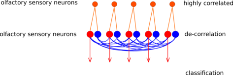
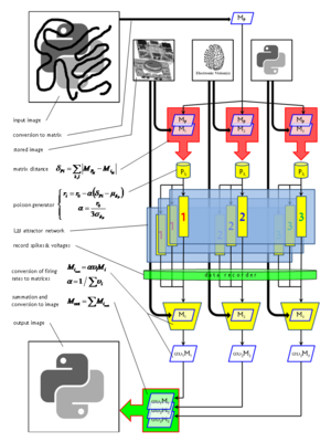
The insect antennal lobe (AL) is the first relay station of olfactory information. Axons from olfactory receptor neurons (ORNs) converge into glomeruli. Glomeruli are small compartments in the AL, where axons from ORNs synapse onto their downstream partners. ORNs carrying the same receptor protein project to the same glomerulus. Hence, a glomerulus can be thought of as a channel representing a specific kind of information about the input, e.g. the presence of a specific chemical feature.
Between glomeruli, there are prominent inhibitory lateral connections. It has been shown that the strength of the lateral inhibition between two glomeruli is proportional to the correlation between their input [1]. We have shown that the concept of lateral inhibition between channels can enhance classification of chemical data points using a simple rate-code based model network [2].
Here we implement this network with leaky integrate-and-fire spiking neurons. The full experiment is described using the simulator-independent modeling language PyNN. Our aim is to run the network on the chip-based prototype neuromorphic hardware system developed within the FACETS project [3]. Such a neuromorphic realization would be a proof-of-functionality showing that the 104-fold speedup compared to real neurons could make a technical application of channel decorrelation feasible.
Schematic of the glomeruli model (red: excitatory, blue: inhibitory). Figure by Daniel Bruederle.
The following changes were applied to [link! the PyNN script originally provided] by Michael Schmuker in order to achieve a hardware-compatibility:
After the above modifications and parameter optimizations had been applied, the pairwise distance of the output patterns could be significantly increased compared to the pairwise distance between the input patterns.
The work will be continued with the aim to implement a spike-based classifier and to extend the set of problems that can be solved with the setup.
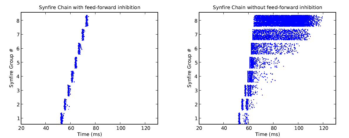
Similar to classical synfire chain models, the INCM/ALUF model consists of a chain of units connected in a feedforward fashion, with a certain delay in between. This allows spiking activity to propagate along the chain in a given direction. However, in addition to this, the INCM/ALUF model implements feedforward inhibition by subdividing each unit into a regular spiking, excitatory (80%) and a fast spiking, inhibitory (20%) population. Inhibitory cells are also activated by feedforward projections of excitatory cells from the previous unit, but project only locally onto the excitatory population of the same unit, with a small delay. This allows a fine control over the duration of spiking in a single column and prevents temporal broadening of the signal as it gets passed down along the chain. In the original model, the inhibition is tuned in such a fashion, that every excitatory neuron gets to spike exactly once, upon activation.
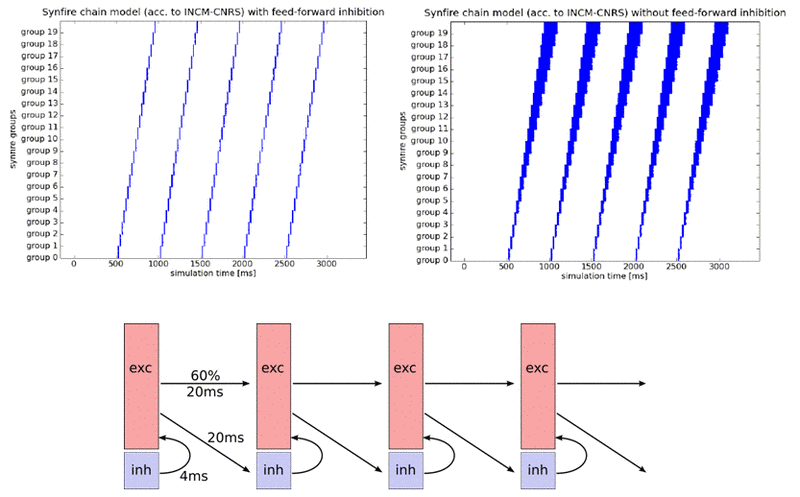
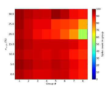
The INCM/ALUF synfire chain is quite sensitive to parameter variations. The feature which is most likely to be affected by hardware imperfections is the single spiking of excitatory neurons upon activation. As a result, we were not able to reproduce this feature on the FACETS Stage1 chip. However, assuming that variations are just as prevalent in biological systems, we believe this feature to not be essential for the evaluation of model functionality. Apart from that, the INCM/ALUF model seems somewhat resistant towards random parameter variations when populations are large enough, as can be seen below for jitter in synaptic weights up to 30% (a realistic figure for our neuromorphic hardware):
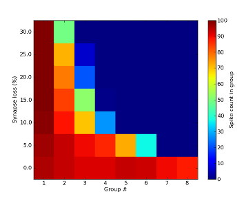
The strongest impact of hardware limitations on the synfire chain comes from synaptic losses. When neuron populations per unit become too large, communication bandwidth limitations will necessarily lead to some synapses being lost in the mapping process. While this only happens for populations much larger than 100 neurons per unit, simulations have yielded a discontinuation of synfire activity for synaptic losses as low as 5%.
Another major difficulty lies within the absence of delays on either hardware system. Since delays are of indispensable importance for the feedforward inhibition, a reliable workaround needed to be found. Ultimately, we were able to modulate the temporal impact of the inhibitory cells by tuning their synaptic properties (weight and time constant).
We have been able to successfully run the INCM/ALUF model on the virtual version of the waferscale hardware with only minor parameter tuning. Interestingly enough, while neurons do not fire as synchronously as in software simulations (because of missing delays which needed to be compensated by tuning synaptic weights), we managed to make them fire only once upon activation. The spread of firing times remains constant throughout the synfire chain.
In order to fit the synfire chain on the FACETS Stage1 chip, populations needed to be significantly scaled down. The Stage1 version of the INCM/ALUF model implemented 8 units with 16 excitatory and 4 inhibitory cells each. Naturally, connection densities and weights needed to be tuned accordingly. In order to simulate background activation, both resting and reset potential were raised towards the threshold potential. Through careful tuning of parameters, even in absence of configurable delays, we were able to achieve firing patterns that were quite similar to the ones from the original model.

[4] Kremkow, J., Perrinet, L., Aertsen, A. and Masson, G.S.. Functional consequences of correlated excitatory and inhibitory conductances. Submitted to Journal of Computational Neuroscience
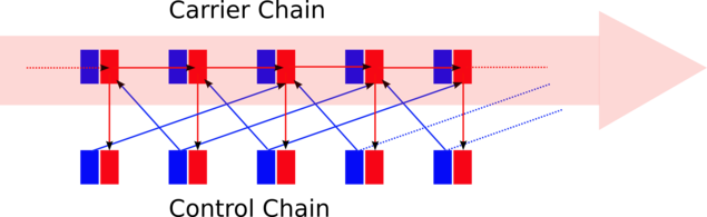
Two parallel chains of neuron populations safely carry forward a bump of firing activity. The carrier chain always has only a maximum of two neighboring populations being active, although within this chain there are excitatory feedforward connections from population to population. The maximum number of two active carrier populations is guaranteed by the control chain. The activity in the control chain is evoked by the activity in the carrier chain, i.e. the activity peak in the control chain runs in parallel to the one in the carrier chain. But activity in control population N imposes massive inhibition to carrier population N-1 and N+2. This allows a feedforward excitation only from carrier population N to N+1. In such a sluice scheme, activity can be passed on in a controlled and isolated way from carrier population to carrier population without any divergence or dispersion effects of the signal. Furthermore, due to the massive inhibition wave preceding every activity wave, interferences with possible ongoing background firing within the network is avoided. The activity signal is forcing its way and can hardly be stopped.
Simplified schematic of the inhibition-guarded activity conveyance (red: excitatory, blue: inhibitory).
The FACETS Stage1 Hardware was used to implement the proposed architecture. After a while of parameter tuning, every population - both in the carrier and in the control chain - was chosen to consist of 7 excitatory and 7 inhibitory neurons. The biggest problem was to guarantee that the controlling inhibition was able to actually suppress all activity in the dedicated carrier populations. This is not trivial since the firing there has to be self-amplifying in order to allow for a self-sustaining activity, which is practically impossible to tune to a reasonably balanced point in such small networks. Hence, the self-exciting firing was hard to stop, but with an appropriate configuration of the reversal potentials, firing thresholds, reset potentials etc. the dynamics in the sub-threshold regime could be tuned such that the impact of inhibition became large enough to fulfill the job. Here is a PyNN script of the currently final version.
The end of the chain was connected to its start, and a short excitatory firing pulse into the first population was sufficient to initiate a firing signal traveling through the chain ring multiple times. See the rasterplot below (acquired from the FACETS hardware) to get an impression of the activity going on.
Inhibition-guarded activity conveyance along a 6-population ring implemented on the FACETS Stage1 hardware system. Figure by Daniel Bruederle and Thomas Clayton.
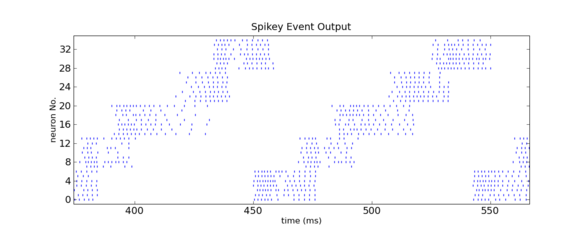
Zoom into the above figure. Figure by Daniel Bruederle and Thomas Clayton.
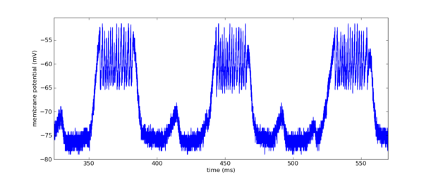
Membrane potential of one of the carrier chain neurons.
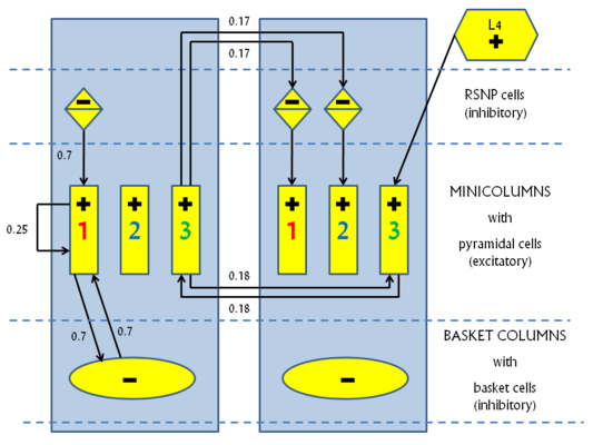
The KTH L2/3 model stays true to its biological archetype by respecting the columnar stucture and the connectivity patterns inside the mammalian neocortex. The basic structure consists of a number of hypercolumns, each subdivided into a number of minicolumns. A so-called pattern contains exactly one minicolumn from each hypercolumn. Until now we have only studied orthogonal patterns (patterns which share no minicolumns), thus making the number of "stored" patterns equal to the number of minicolumns per hypercolumn.
Every minicolumn contains a population of excitatory pyramidal cells and a population of inhibitory RSNP (regular spiking non pyramidal) cells. The RSNP cells belonging to a minicolumn project only onto the pyramidal cells from the same minicolumn. The pyramidal cell population from one minicolumn projects both back upon itself and also onto all pyramidal populations from all minicolumns belonging to the same pattern. This allows for activity to spread throughout an entire pattern when only part of it is activated.
Patterns compete among each other by making use of two different WTA-like mechanisms. Each hypercolumn implements a "soft" WTA module by means of an inhibitory pool of basket cells which receive excitatory projections from all minicolumns inside the hypercolumn and, in turn, project back onto all minicolumn pyramidal populations. A long-range, "strong" WTA is achieved by each minicolumn pyramidal population projecting onto the RSNP cells of all the other minicolumns that do not belong to the same pattern, which, in turn, inhibit the pyramidal cells from their own minicolumn, as described above.
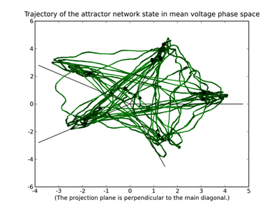
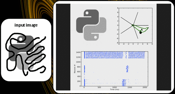
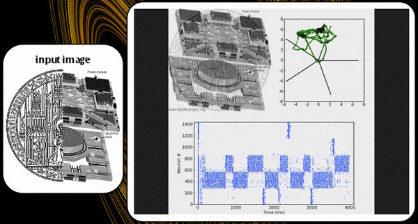
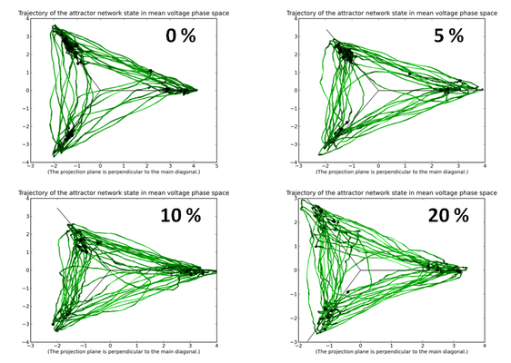
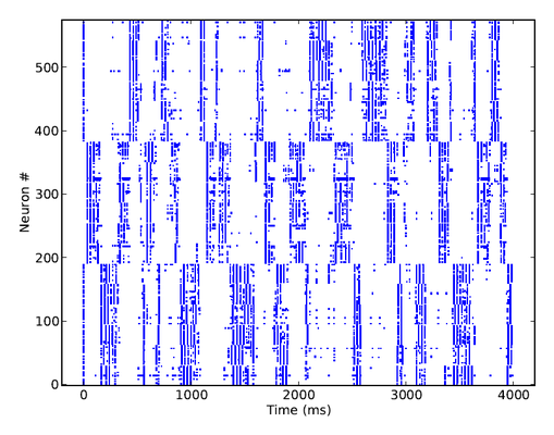
Below is a raster plot of the activity of the network, when all pyramidal cells are excited by individual Poisson inputs of the same rate. Whenever an attractor becomes stronger than the others (which happens randomly), it completely suppresses their activity, for a short period of time. Pyramidal cells in an active attractor are in a so-called UP-state, where their average membrane potential is a few mV above its rest value. When plotting the trajectory of the system in potential space, a projection along the main diagonal will yield a typical star-like pattern.
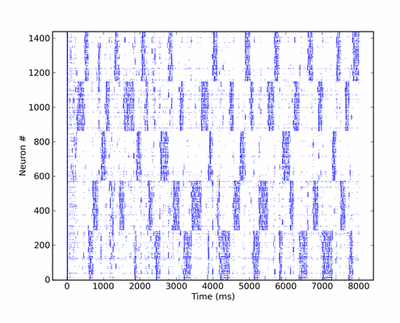
The synaptic plasticity mechanisms are chosen such as to prevent a single attractor from becoming prevalent. Excitatory-to-excitatory synapses are modeled as depressing, which weakens the mutual activation of active pyramidal cells in time, while inhibitory-to-excitatory synapses are facilitating, thus increasing the self-inhibition of pyramidals via the basket cells. Both mechanisms have the effect of weakening attractors over time, such that, in contrast to a classic WTA network, also weaker patterns may become active at times.
The KTH model exhibits two distinguishing functional features. First of all, due to the mutual excitation of pyramidals from one pattern, it suffices to activate only a small part of it in order to have activity throughout the entire pattern, which amounts to a pattern completion functionality. We have demonstrated this in a software setup, as can be seen in fig. X and Y.
Secondly, due to competition among patterns, the network will give rise to a pattern rivalry effect, with the network switching between the "strongest" patterns. The implemented plasticity mechanisms prevent a single activity pattern from taking over the network, thus enabling also weaker patterns to become active, although, of course, for a shorter time. Pattern dwell time thus becomes proportional to pattern activation strength.
Before implementing such a complex network onto a hardware substrate, we had to evaluate the expected distortions arising from the biology-to-hardware mapping and, if possible, find corresponding compensation mechanisms.
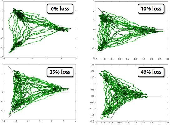
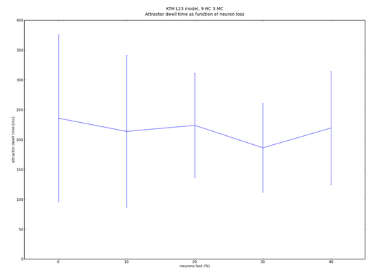
The most prohibitive hardware constraint concerns the communication bandwidth among its components, which has an immediate effect on the connectivity of the implemented network. When large numbers of synapses are lost in the mapping process, the network responds with decreasing attractor stability, ultimately becoming effectively random in its response to stimuli.
Another prohibitive factor resides within the variations which are inherent to the photolitographic process used in manufacturing VLSI hardware. These can result in supposedly identical components to behave significantly differently from each other. In neurophysiological terms, this might result, for example, in synaptic weights being scattered around their intended value by up to 30%.
Fortunately, a properly configured KTH network is robust to both synaptic jitter and small amounts of synaptic loss.
We were able to prove that the robustness of the network increases with its size. In order to scale the network to any desired size, we have devised a set of simple scaling equations, which allow us to maintain its functionality, while choosing an almost arbitrary number of hypercolumns, minicolumns or neurons per column.
In particular, we have found out that the number of pyramidal neurons per hypercolumn is not essential to the functionality of the network. This has been of extremely helpful when "miniaturizing" the network so it would fit onto our Stage I hardware - the "Spikey" chip.
Since the virtual hardware does not suffer from process variations, these were not a factor in the implementation of the model onto this substrate. However, the communication bandwidth still could have posed a problem, as the communication structure among the different hardware units is accurately reproduced. Nevertheless, the virtual hardware can comfortably fit a KTH model with approximately 1000 neurons and simulate it in a time comparable to state-of-the-art software simulators. The implementation was insofar a success, as the hardware-emulated model behaved very similarly to the corresponding software simulation.
The FACETS Stage1 chip suffers from several limitations which have made the implementation of such a complex model a challenging task.
The most obvious limitation is its size. Since it only offers 192 neurons, the network has to be scaled down to unusually small dimensions in order for it to fit on the chip. We have chosen a setup of four hypercolumns with three minicolumns each. RSNP populations had 2, pyramidal 14 and basket 6 neurons. This amounts to a total of exactly 192 neurons.
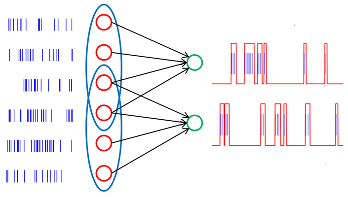
The second, but essential limitation lies within the limited available input bandwidth. With the entire chip occupied by the network, only 64 separate input channels remain available, with a maximal spiking frequency of about 80 Hz each. With 144 pyramidal neurons needing to be stimulated at about 200 Hz each, it was obvious that independent stimulation was no longer an option.
Specifically for such cases, where a limited number of inputs poses a problem, we had previously designed an algorithm for mapping a small number of inputs to a large number of outputs while keeping the resulting neural activity correlations at a minimum (Petrovici and Bill, to be published 2010). With the help of this tool, we were able to find a 3-to-1 mapping from inputs to neurons, with a pairwise overlap of at most 1 inside attractors and 0 otherwise. Thus, we were able to provide the necessary stimulus for the KTH model on Spikey.
With synaptic plasticity not yet adequately available on the FACETS Stage1 chip, we were forced to eliminate this mechanism from the model, while trying to maintain its functionality. Through a careful tuning of synaptic weights, this was, finally, achieved, albeit with a grain of sand: in order to facilitate a switching between patterns (in contrast to a standard WTA network, where the strongest pattern would remain active indefinitely) we had to accept a small deviation from the original model: by slightly increasing the input weights, we have made the on-chip network a bit more input-driven than its biological counterpart.
Finally, due to its small size, the average number of connections per neuron was necessarily smaller that in the original model. However, this was relatively straightforward (though not easy) to compensate by an adequate tuning of neural resting and reset potentials.
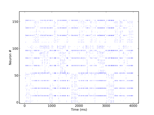
All of this being done, we were ultimately able to run a KTH model simulation on the Stage1 chip, with the same qualitative behavior as a corresponding software simulation.
The quintessential idea behind the liquid state machine, as proposed by Wolfgang Maass et al. [6], is to perform nonlinear operations on a given input by first projecting it into a high dimensional state space (the "liquid"), which can then be analyzed by means of linear separation techniques (e.g. a perceptron). The liquid itself doesn't necessarily need to be implemented as neural network, but it has to be sufficiently complex so it can fulfill two requirements. First, the separation property requires the liquid to assume significantly different states, even for stimuli which lie closely together in input space. The second property relates to the ability of the liquid state to reflect information about past states. The readout is usually implemented as a memoryless circuit and needs to satisfy the so-called approximation property, i.e. its capability of processing different liquid states into different outputs. This can be realized for example by a supervised learning algorithm. This combination of a high-dimensional liquid and a linear readout can be shown to offer, under idealized conditions, universal computational power.
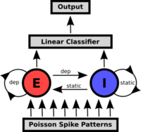
A prepared Poisson pattern is presented to the liquid consisting of a recurrent excitatory and inhibitory population. The linear classifier is trained to perform a pattern recognition task on the liquid's response.
The liquid is implemented as a network of 192 neurons on the FACETS Stage1 hardware with 75% excitatory and 25% inhibitory neurons. The network structure is based on the self stabilizing network presented in [7] and [8]. Since, at any time, the network state is affected by its past, a fading memory mechanism is inherent to this setup. For the readout software perceptrons with a delta-rule learning algorithm are used.
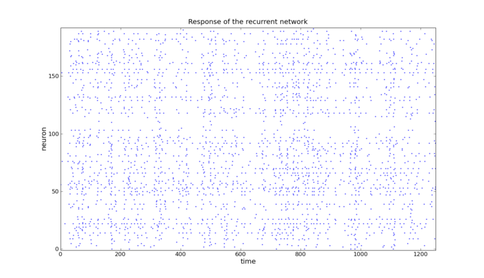
Due to the self stabilizing properties of the underlying network architecture the liquid's activity always stays within a certain range
The input is generated from two different Poisson spike trains of equal rates. For each interval of 50ms in a total of 1250ms a snippet from one spike train or the other is chosen. 1000 of these patterns were fed into the liquid and the output convoluted with an exponential function was presented to the perceptrons. The perceptrons were trained to distinguish between the patterns in one of the intervals each. For the process of training 800 spike trains were used whereas 200 were used to test the performance.
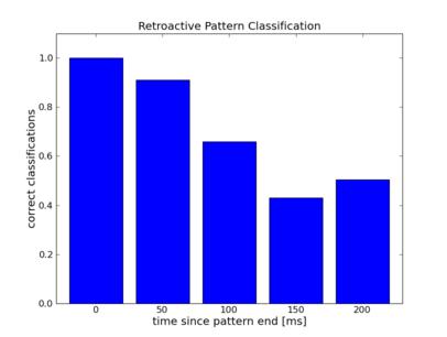
As one would expect the error rate increases with distance between input interval and readout time.
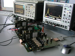
The goal of the project is to directly connect the Dynamic Vision Sensor (DVS) [9] to the FACETS hardware system (FHW).
The FHW is a modular system, where several artificial neural network chips mounted on individual boards are combined to form a larger network. They are interconnected by means of a digital network for which FGPAs on the same board provide access. The FACETS Stage1 chip is bonded on a daughter-board, which is plugged into the FPGA-board.
The idea for this project is to replace one of the daughter-boards with an adapter connecting to the DVS and then use the digital network to forward spike-events to another node, where they are sent to the Stage1 chip. The physical connection to the DVS uses the CAVIAR standard 40-pin connector [10]. To accommodate for the different voltage levels of DVS (3.3V) and FPGA (2.5V) 100 Ohm series resistors were inserted at the FPGA side of the cable. They limit the current flowing through the ESD circuits on the FPGA pin. To synchronize the asynchronous AER signals from the DVS to the internal FPGA clock, two registers in series are used. This way the probability of metastability at the output register is reduced.
The translation between DVS events and the FHW internal event representation is implemented on the FPGA connected to the sensor. From the point of view of the DVS the FPGA behaves like a normal AER receiver. Because the connection is unidirectional this comes down to implementing the four-phase handshake used by the AER standard. Because it was observed that data signals are not reliably asserted at the negative edge of the active-low REQ-signal, sampling is done with the rising edge of REQ. To the internal networking logic the translation layer appears just like a normal Stage1 chip. So all routing mechanisms can still be used unchanged. The task of the translation layer therefore is to map the DVS event address, which encodes Y and X coordinates, as well as polarity of one pixel, to Stage1 chip compatible neuron numbers. The latter span two ranges from 0 to 191 and from 256 to 383. To achieve this a lookup-table implemented in FPGA RAM blocks is used. The table contains one entry for every possible DVS event, which maps it to the aforementioned neuron number ranges. From there on the usual routing mechanisms deliver the event to the destination FPGA and Stage1 chip.
Because the DVS is a real-time sensor with firing rates of up to 100 Hz per pixel, excitation of the accelerated neurons of the FHW (speed-up factor of 10000) is expected to be difficult. Therefore, the lookup-table additionally contains a four bit multiplication field. When set to a value higher than one, multiple events are generated sequentially.
In its maximum configuration the lookup-table is 32768 x 13 bit or 52 KiByte in size, which is about half the dedicated RAM resources on the used FPGA. To allow for future RAM-intensive extensions of the design, the lookup-table is parametrized by the number of bits per pixel coordinate to use. So the number of entries can be dramatically reduced by virtually reducing the resolution of the camera.
The most elaborate test of the interface between FACETS hardware and Dynamic Vision Sensor used the Event loopback mode of the Stage1 chip. In this mode the Stage1 chip forwards incoming events directly to the output, bypassing the analog neural network part. The returned events are recorded on the attached FPGA and can be read out from the controlling PC. This allows to directly monitor what is forwarded to the chip. Using this mode the functionality of the physical interface and the translation layer was verified. The test unfortunately does not allow to quantize the quality of the connection. So the rate of event loss and bit errors can not be measured. The measurements (see figures) however show that events from all pixels of the sensor are received. When presenting a scene with more activity, e.g. by waving a hand in front of the DVS, the mean rates of the received spike trains increase as well.
To perform a processing task on the chip it has to be configured according to the desired neuronal architecture. However it was not possible within the time frame of the workshop to modify the existing control software to correctly configure the chip. This is probably due to an incompatibility with networking features in the FPGA and the software.
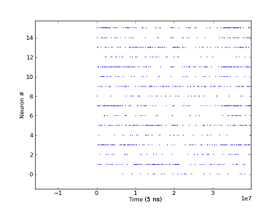
Spike-trains received via event-loopback from the FACETS Stage1 chip. The 16 neurons are mapped to 4x4 fields of pixels on the DVS, virtually reducing the resolution. The retina is stimulated by waving a hand in front of the camera.
[10] CAVIAR connector standard
The development for a soft-WTA ring according to a paper by E.Chicca et al. [11] was already started during last year's CNE workshop by Daniel Bruederle and Eric Mueller.
In the applied setup, two gaussian bumps of excitatory spike stimulation are applied to the ring. The global inhibition results in a competition of the two stimulated regions for activity. If the ring is configured correctly, small differences in the applied stimulation strengths result in large differences in the response peaks along the ring ("soft" winner-take-all).
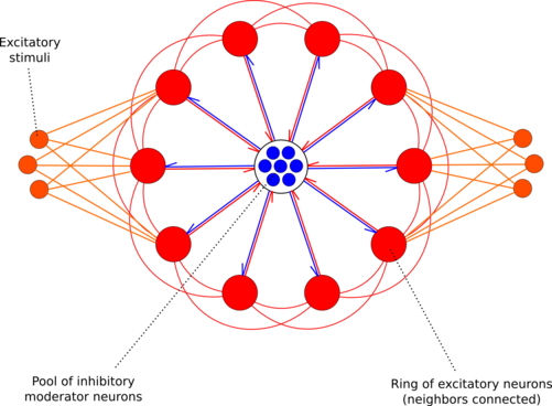
Winner-Take-All ring as implemented on the FACETS Stage1 hardware (red: excitatory, blue: inhibitory, orange: excitatory stimuli). Figure by Daniel Bruederle.
The architecture as depicted in the schematic above was implemented for the FACETS Stage1 hardware by creating a PyNN script with a graphical user interface (using PyQT and Qwt) by Daniel Bruederle and Simon Friedmann. A screen-shot can be seen below. It is easy to tune the involved parameters such that the functionality of two competing activity bumps, which amplify the difference of the applied input rates, can be observed.

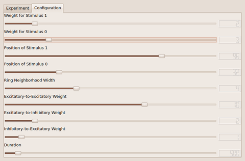
Screenshots by Daniel Bruederle and Simon Friedmann.
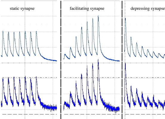
Short Term Plasticity (STP) is besides Spike Time Dependent Plasticity (STDP) one of the two synaptic plasticity mechanisms implemented in the FACETS Stage1 hardware. It is possible to choose between a facilitating and a depressing mode for each individual synapse driver, which drive up to 192 synapses sharing the same source neuron, which corresponds to an axonal plasticity mechanism. Furthermore the strength of the STP mechanism can be adjusted. We implemented the access to this feature in the PyNN 0.6 conform way. The Tsodyks-Markram-Mechanism parameters in PyNN become translated to the appropriate parameters in the hardware domain. The original STP mechanism provides 3 parameters: U, tau_rec and tau_facil. The usable efficacy U is automatically mapped to the most appropriate of 4 possible values in the hardware STP implementation. In the hardware one has to choose between either depression or facilitation, therefore only one of the two time constatns can be realized in the hardware. When using the Tsodyks-Markram mechanism in the pyNN.hardware one of the two time constants has to be set to zero (this determines the mode of STP).
In the hardware the time constant is modulated by the current I_rec, which is set by adjusting Vdtc. In order to find a suitable transformation of the tau_rec / tau_facil into its hardware counterpart, a calibration method was developed. Measurements revealed that the time constant is actually not adjustable within the desired range (100 - 1000 ms) as the range of Vdtc may only provide time constants corresponding to values below 150 ms in biology. The reason for that might be that the temporal dynamics of STP circuits in the latest FACETS Stage1 version (# 4) have not been adapted when reducing the speedup-factor from 100000 to 10000. Further measurements and examinations of this problem will be undertaken back in Heidelberg.
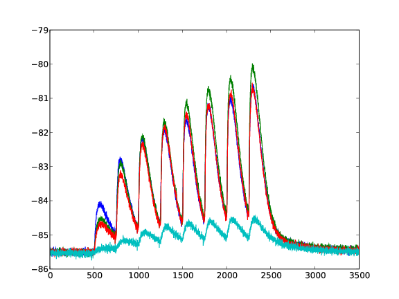
Response of a facilitating synapse on the neuron's membrane potential. 4 Different values for U are plotted (averaged over 50 runs).
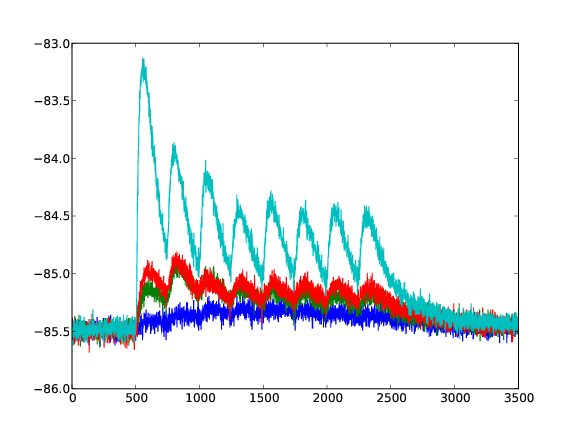
Response of a depressing synapse on the neuron's membrane potential. 4 Different values for U are plotted (averaged over 50 runs).
Networks of nonlinear integrate-and-fire neurons (here: Adaptive-Exponential I&F) can show self-sustaining activity exhibiting irregular and asynchronous spiking (AI-states) [12]. If there is a self-sustained AI-state strongly depends on the network size and the network size.
The network consists of 80% excitatory pyramidal cells (PY) and 20 % inhibitory interneurons (IN) cells. Inhibitory cells are fast-spiking (FS) and excitatory are regular-spiking (RS), implementing spike-frequency adaptation. At a network size of 2000 each cell is randomly connected to 2 % of the network. When scaling the network down, the connectivity increases with the same factor, such that every neuron has a constant fan-in independent from the network size. 5 % of the cells get initially stimulated for 50ms, then the network is left to its own.
If the network is self-sustaining showing AI-states depends on several factors: - network size: a larger network favours self-sustaining AI activity - spike frequency adaption of PY-cells: a lower value of AdEx-Parameter b (b=0.005 nS(weak adaptation) or 0.05 nS(strong adaption)), benefits AI-states. At strong adaptation the network activity dies out. - low-threshold spiking neurons (LTS): by replacing a fraction(between 5 - 30 %) of the PY cells by LTS cells (by setting adaptation parameter a=2 nS and b=0), the network shows self-sustaining AI-states at smaller sizes and with stronger adaption in the other cells.
By combining two of these cortical networks (Layer A and Layer B), transient Up- and Down-States can be achieved. Layer A consisting of 2000 cells is not self-sustaining for a strong adaption in PY cells (no LTS cells are included) as a stand-alone. In contrast Layer B with only 500 cells is self-sustaining with AI-states as a stand-alone due to 10 % LTS neurons in the excitatory population.
Excitatory cells of each Layer connect to 1 % of all neurons of the other Layer. With this interconnection of the network transient Up-and-Down States emerge. When the activity in Layer A starves, it gets re-activated from the input of self-sustaining Layer B.
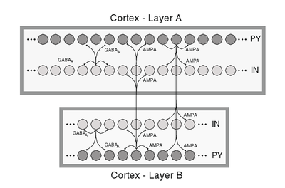
Schematic of a 2 Layer cortical network structure.
The aim for this workshop was to implement this network model on the executable system specification of the FACETS Stage2 hardware. As this "virtual hardware" and the higher software layer for the operation of it still have some constraints, some modifications had to be made to the model. As the maximum reliable network size on the virtual hardware is 2048, the network had to be scaled down. A given pyNN - script of this Network Model was changed such it can be arbitrarily scaled up and down, reproducing the same activity patterns. Anyway there is a limit of down-scaling, as Layer B of the cortical network model has to be self-sustaining, which requires a minimum size (~300). A plot of the network activity of a model with a total of 2000 cells simulated with NEURON is shown in the following. One can easily recognize time intervals of high actiivity (UP-State) and nearly no activity (DOWN-State) in the rasterplots.
Output of 2 Layer cortical network exhibiting Up and Down States
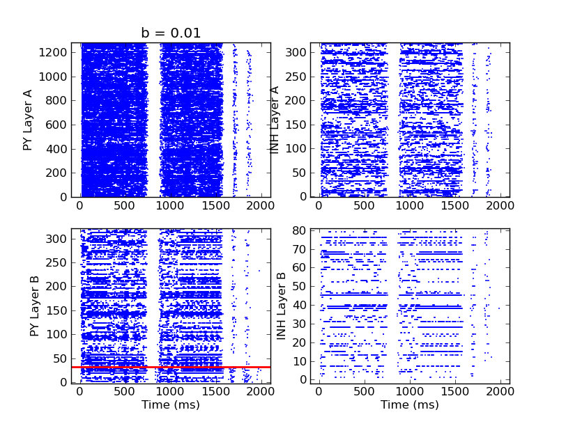
Up- and Down-states in 2 layer cortical network. Top: PY (left) and IN (right) spikes in Layer B. Bottom: PY (left) with a fraction of LTS (below red line) and IN (right).
A successful implementation of this model on the virtual FACETS hardware could not yet be achieved, while the self-sustaining AI states in a single cortical Layer can be reliably reproduced with emulations on the virtual hardware. A systematic analysis of the first task and possible bugs in all software layer is work in progress.
A single neuron is repetetively stimulated via N equidistant spikes running into the cell via N different excitatory synapses. All synapses are initialized with the same weight, such that the stimulated neuron fires an output spike at a late point during this stimulation sequence - at least in the beginning. After some repetitions of applied input patterns, though, the applied STDP rule results in an ongoing change in both the synapse weight distribution and the output spike time: Synapses that deliver "early" input spikes are strengthened as long as they send their input spike before the output spike is released. Consequently, the output spike is continuously shifted towards earlier points in time. Those synapses that deliver their input spikes after the output are weakened. After a certain number of applied input sequences, only the first synapses have weights significantly above zero, and the output spike is generated in a very early phase of the input pattern already.
Here is a PyNN script written by Olivier Bichler that performs exactly the above setup. It has been tested with NEST and automatically generates two plots: Both the output firing time of the stimulated neuron as well as the synapse weight distribution as a function of the applied input pattern repetition.
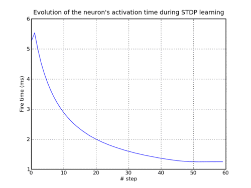
Development of output spike timing as a function of applied input pattern sequences (under STDP learning).
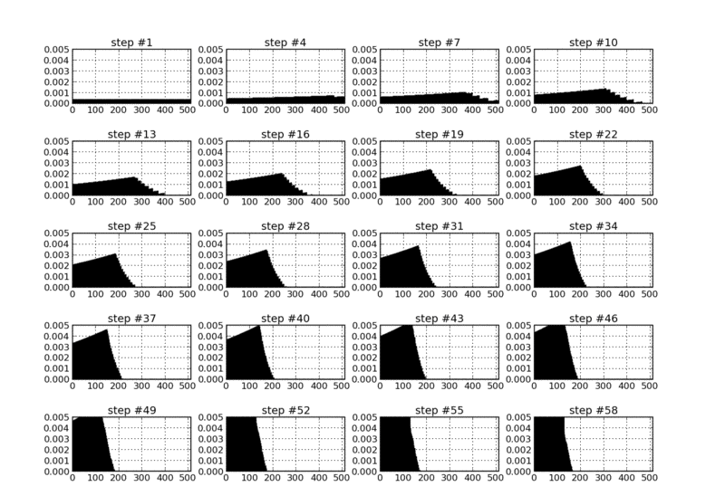
Synapse weight distribution as a function of applied input pattern sequences (under STDP learning).
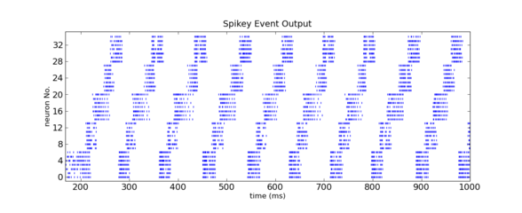
With the "Cognition - How would we know if we saw it?" - Workgroup in mind and with a little spare time on our hands, it occurred to us that we should be able to find a way to make the FACETS Stage1 hardware talk to us - in "spike language", of course. It would also be a nice way of showing off the capabilities of the chip in terms of versatility and adjustability, as the precise representation of characters in a raster plot would require quite some amount of tuning of neuron parameters.
In order to make the task a little more interesting, we decided upon the representation of characters within a raster plot, instead of a topological arrangement of spiking neurons. As the axes of a raster plot represent time and neuron number, respectively, we needed a precise timing of spiking activity in order to create the pixels necessary for writing in a raster plot.
As nearly any character can be represented on a 5x5 pixel lattice, we have chosen 5 independent (not interconnected) populations of neurons to represent the vertical 5 pixels (y axis of the raster plot). Inspired by the architecture of our synfire chains, we have subdivided each of these populations into two subpopulations, an excitatory one for pixel representation and an inhibitory one, which controls the activity of the excitatory neurons and thus the width of the pixels in time (x axis of the raster plot). The excitatory and inhibitory subpopulations project onto each other with given probabilities, no self-projections are allowed.
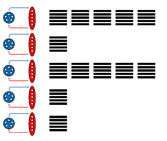
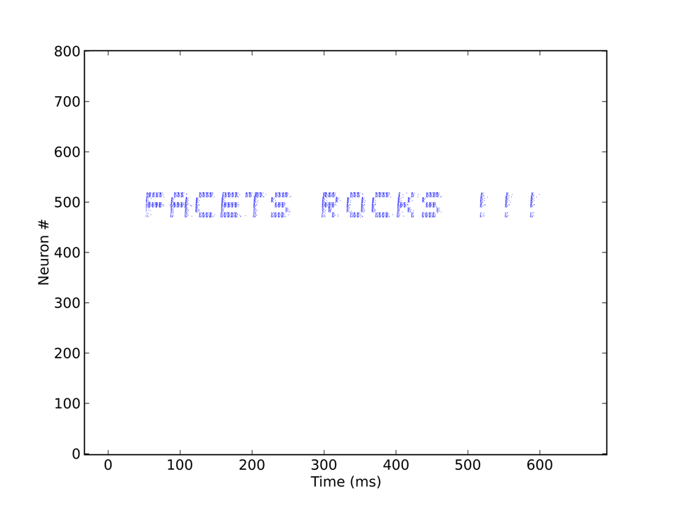
Each "pixel" needs to be stimulated by a single spike to become activated. Thus, the input, consisting of a character string, e.g. "Facets rocks !!!", is first translated into a sequence of spikes which are then sent to the appropriate populations. The corresponding output, coming directly from the Stage1 chip, can be seen below.

 HOME
HOME
