Next: Failsafe daisy chaining with Up: The readout Previous: The readout
![]()
![]()
![]()
![]()
Next: Failsafe daisy chaining with
Up: The readout
Previous: The readout
Helix128-2 chips can be daisy-chained in order to save cost in following stages. A diagram of several Helix128-2.0/2.1 chips in a daisy chain is given in fig. 13. The following discussion holds for Helix128-2.0/2.1; Helix128-2.2/2.3 makes use of an identical scheme but with reversed token direction (i. e. the chips in a daisy-chain are read out from top to bottom). Failsafe token pads as well as pads for a reversed-polarity token have been added for compatibility with the future Helix128-3.0.
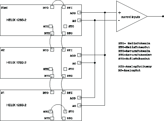 |
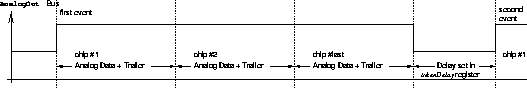
The first or leading Helix128-2 in the daisy chain generates the primary token at the output of SufixTokenOut. By bonding SufixTokenOut to HelixTokenIn on the first chip the token is transferred to the readout multiplexer which starts transmitting the analog values on the common analog busses (the outputs of chips not posessing the token are switched to high ohmic). After the final values of chip #1's analog data the token is output on HelixTokenOut of chip #1 to HelixTokenIn of chip #2. Upon receipt the second chip's multiplexer starts sending data since the HelixTokenIn and SufixTokenIn pads are internally connected (the SufixTokenIn pad has been added for ease of bonding). By bonding from HelixTokenOut to ReturnTokenIn on the daisy chain's last chip the token is fed into the token return path thus being directly transferred to the leading chip of the chain (since ReturnTokenIn and ReturnTokenOut are internally connected). By receipt of the returning token the leading chip is signaled the end of the transmission. The signal on the common output bus is illustrated in fig. 14.
If only a single chip is operated, SufixTokenOut must be bonded to SufixTokenIn and HelixTokenOut to ReturnTokenIn.
![]()
Martin Feuerstack