 (PPM) carries the
functionality required to transform analog calorimeter signals into digital
values of "transverse energy". These are transmitted as serial data-streams
to the subsequent processors, where "object-finding" is performed.
(PPM) carries the
functionality required to transform analog calorimeter signals into digital
values of "transverse energy". These are transmitted as serial data-streams
to the subsequent processors, where "object-finding" is performed.- The "Cluster Processor" ( -> RAL) identifies objects, whose energy-deposits are contained in a small space-region of the calorimetry. Examples of such objects are photons, electrons, tau-leptons ...
- The "Jet/Et Processor" ( -> Mainz) looks for extended objects like particle-jets, the sum of "missing transverse energy" ...
- Hence, two data-paths are formed at the PPM's output.
- The first represents energy-deposits on a "fine" granularity (0.1 in pseudo-rapidity * 0.1 in azimuthal angle) adequate for the "Cluster-Processor".
- The second path shows energy-deposits on a "coarse" granularity (0.2 * 0.2) suitable for the identification of extended objects in the "Jet-Energy Processor".
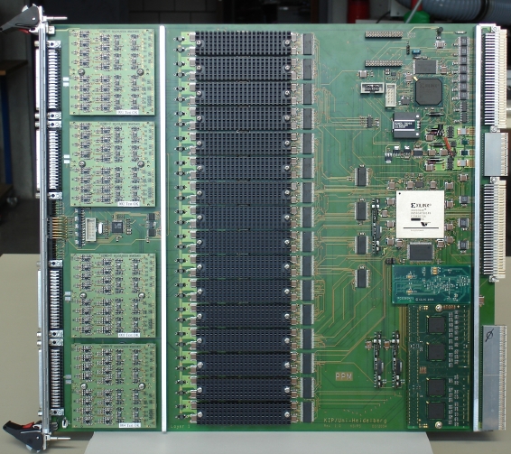
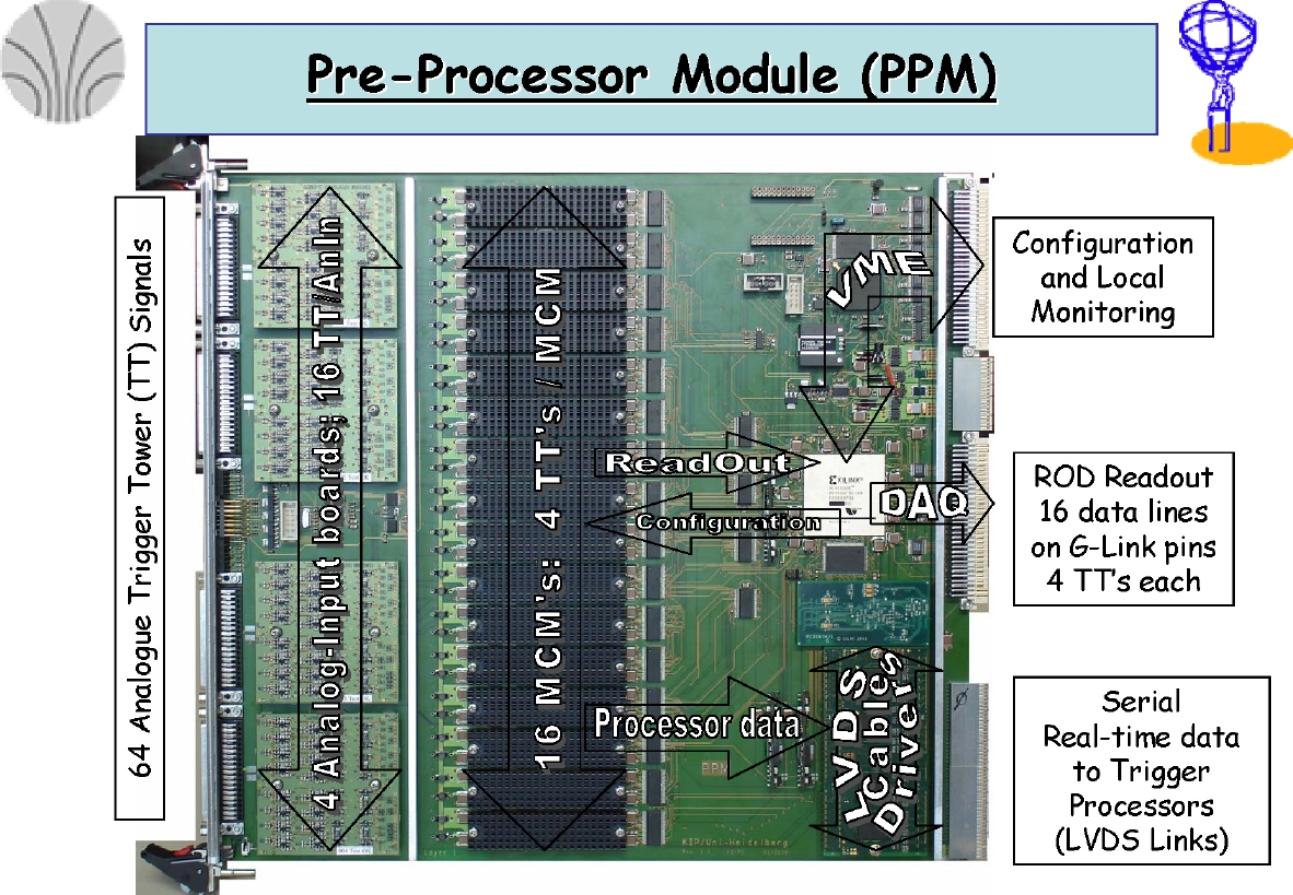
The analog input signals (more than 7200 in total) enter the PPMs
at the front-panel. Each Module receives 64 calorimeter cells as
differential signal pairs. Pre-processing each signal implies several
steps before digital data can be passed on to the object-finding processors:
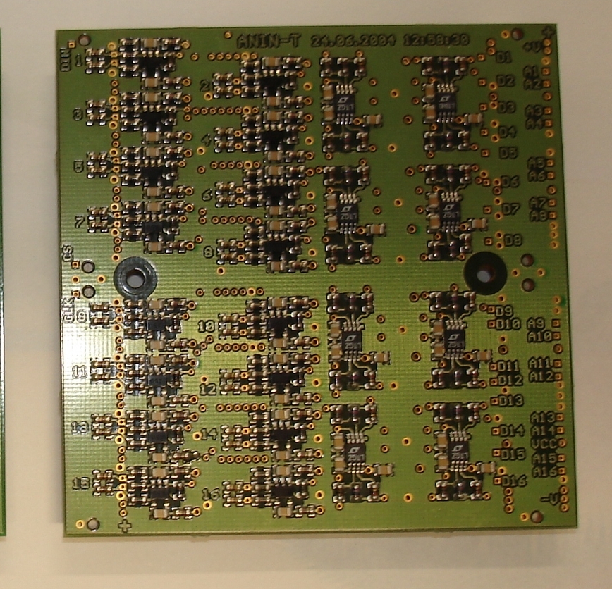
- Conditioning the analog input for digitization.
- Determination of the time to attribute the signal to the "bunch-crossing" in the storage-ring accelerator, where the collision took place. One possibility is the application of a threshold in a discriminator to mark the point in time.
- Digitization to a 10-bit value with exact sampling on the signal's peak.
- Alignment of all pipelined values in terms of "bunch-crossing" clock-ticks. The detector is huge, hence signal propagation to the central trigger location has a much larger spread than the clock-interval.
- Fast monitoring of trigger cell occupation by means of histogramming in hardware.
- "Bunch-Crossing" Identification (BCID) for ALL domains of signal-amplitude (linear, saturated).
- Fine-Calibration of the transverse energy by means of a Look-Up Table (LUT).
- Multiplexing channels, where possible, to economise.
- Adding cells to coarse granularity for detection of "extended" objects (particle-jets, transverse energy in hemispheres).
-
Serialization of the data-streams for transmission, because parallel
transmission of 7200 channels is ruled out by cable-logistics.
----- AND ----- - Provision of event-by-event readout. Setting-up, calibrating and on-line monitoring of such a complex system can only be achieved by means of computerized tools. Also, verification of a trigger decision in a quantitative off-line analysis is only possible when the raw input data are available.
 (
(